

Controlling LED’s using IR Remote Control – Arduino Project
Contents
This article allows you to turn ON and OFF LED’s using a cheap IR remote control. Here we used an available IR Arduino library so it was pretty easy to decode the signals transmitted by the infrared remote.
The LED’s which are connected to Arduino will be controlled by IR Transceiver module. IR Transmitter i.e., Remote transmits unique code to IR sensor wirelessly. IR sensor receives that signal and controls the LED’s which are connected to Arduino according to Code.
Required Components
- IR sensor
- Arduino Uno
- 4 X Led’s
- 4 X 220 ohm resistors
- Remote
- Connecting wires
- Breadboard
Hardware
Circuit Diagram

Circuit Diagram Explanation
First of all, connect the LED’s with Arduino. Connect the positive side of the four LED’s to the pins 7, 6, 5 and 4 of Arduino and the negative side of LED’s to the GND of Arduino through the 220 ohm resistors. The resistors are necessary because they prevent the excess amount of current from flowing through the LED’s.
After that, make the connections of the IR sensor with the Arduino as follows
- Connect the negative of IR sensor to the GND of Arduino.
- Connect the positive of IR sensor to the 5V pin of Arduino.
- Connect the signal pin of IR sensor to the pin 8 of Arduino.
Software
Arduino Code
#include <IRremote.h>

int receiver_pin = 8;
int first_light_pin = 7;
int second_light_pin = 6;
int third_light_pin = 5;
int fourth_light_pin = 4;
int led_case[] = {0,0,0,0};
IRrecv receiver(receiver_pin);
decode_results output;

#define code1  48703
#define code2  58359
#define code3  6375
#define code4  25979

void setup()
{
  Serial.begin(9600);
  receiver.enableIRIn();
  pinMode(first_light_pin, OUTPUT);
  pinMode(second_light_pin, OUTPUT);
  pinMode(third_light_pin, OUTPUT);
  pinMode(fourth_light_pin, OUTPUT);
}

void loop()
{
  if (receiver.decode(&output))
  {
    unsigned int value = output.value;
    switch(value)
    {
      case code1:
      if(led_case[1] == 1)
      {
        digitalWrite(first_light_pin, LOW);
        led_case[1] = 0;
      }
      else
      {
        digitalWrite(first_light_pin, HIGH);
        led_case[1] = 1;
      }
      break;
      case code2:
      if(led_case[2] == 1)
      {
        digitalWrite(second_light_pin, LOW);
        led_case[2] = 0;
      }
      else
      {
        digitalWrite(second_light_pin, HIGH);
        led_case[2] = 1;
      }
      break;
      case code3:
      if(led_case[3] == 1)
      {
        digitalWrite(third_light_pin, LOW);
        led_case[3] = 0;
      }
      else
      {
        digitalWrite(third_light_pin, HIGH);
        led_case[3] = 1;
      }
      break;
      case code4:
      if(led_case[4] == 1)
      {
        digitalWrite(fourth_light_pin, LOW);
        led_case[4] = 0;
      }
      else
      {
        digitalWrite(fourth_light_pin, HIGH);
        led_case[4] = 1;
      }
      break;
    }
    Serial.println(value);
    receiver.resume();
  }
}
Code Explanation
First of all, we need to include the library for the IR sensor and IR remote. Then we initialized the pins where we connected the led’s and set the initial state of the led’s as off state.
#include <IRremote.h>
int receiver_pin = 8;
int first_light_pin = 7;
int second_light_pin = 6;
int third_light_pin = 5;
int fourth_light_pin = 4;
int led_case[] = {0,0,0,0};
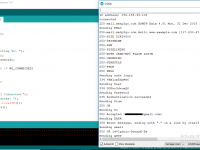
Then we defined the code for each button through which we want to control the led. If you are running the Arduino code for the first time then upload the Arduino code as it is and open the Serial monitor. Press the button from the remote and a code will be shown on the serial monitor for each button.
#define code1  48703
#define code2  58359
#define code3  6375
#define code4  25979
In the setup function, we have made the led pins as output pins because we will give the output to the led’s through that pins.
pinMode(first_light_pin, OUTPUT);
pinMode(second_light_pin, OUTPUT);
pinMode(third_light_pin, OUTPUT);
pinMode(fourth_light_pin, OUTPUT);
Whenever a button is pressed, a code is received by the IR sensor and is given to the Arduino. The Arduino will then compare it to the already saved codes and if any of the code will match then it will turn on the led connected to that code. If the LED is already light up and the same button is pressed again then the led will go down.
if (receiver.decode(&output))
{
  unsigned int value = output.value;
  switch(value)
  {
  case code1:
  if(led_case[1] == 1)
  {
    digitalWrite(first_light_pin, LOW);
    led_case[1] = 0;
  }
  else
  {
    digitalWrite(first_light_pin, HIGH);
    led_case[1] = 1;
  }
  break;
  case code2:
  if(led_case[2] == 1)
  {
    digitalWrite(second_light_pin, LOW);
    led_case[2] = 0;
  }
  else
  {
    digitalWrite(second_light_pin, HIGH);
    led_case[2] = 1;
  }
  break;
  case code3:
  if(led_case[3] == 1)
  {
  digitalWrite(third_light_pin, LOW);
  led_case[3] = 0;
Working
Whenever a button is pressed on the IR remote, an IR led blinks thousands of time in a fraction of second and sends that data to the IR receiver in the coded form. The IR receiver receives this signal and sends it to Arduino.
Each button has a unique code. So we have saved the codes for the buttons to which we want to control the LED’s in the Arduino code. Now whenever a button is pressed, then an unique code will be received by the IR receiver and sends to Arduino. Then the Arduino compares this received unique code with the saved codes. If any of the code matches with the Arduino pre-stored code then Arduino will turn ON the appropriate LED light.
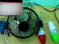
Practical Implementation

