

IR Remote Control for Home Appliances
IR Remote Control for controlling home appliances can be easily made using Decade Counter CD4017, 555 Timer and TSOP1738 infrared receiver. By using this circuit you can easily control your home appliances using your TV, DVD Player remote control or using a remote control circuit described here.
Remote Control Receiver Circuit Diagram
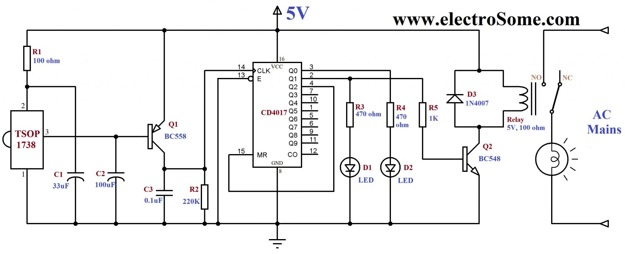
2nd and 1st pins of TSOP1738 are used to give power, Vcc and Gnd respectively. 100Ω resistor and 33μF capacitor is to suppress power supply disturbances. When IR rays at 38KHz falls on TSOP1738, output (3ed pin) goes low, since the output is active low. This output is amplified by the transistor Q1 and is given to the clock input of CD4017. 16th and 8th pins of CD4017 is used to give power Vcc and Gnd respectively. Enable (13th pin) is tied to Gnd to enable the IC, since it is an active low input. Output Q2 (4th pin) is connected to Reset MR (15th pin) to make CD4017 a bistable multivibrator. During the first clock signal Q0 becomes high, second clock signal makes Q1 high (Q0 becomes low) and the third clock signal makes Q0 high (since Q2 is connected to MR, third clock signal resets the counter).
Note : CD4017 is a Decade Counter with Decoded Outputs, ie Q0 becomes high first, then Q2, then Q3 and so on.
Lets assume the counter is Reset state (Q0 high and others low). When the remote is pressed, clock signal is generated which makes Q1 is high. Thus LED D1 glows, transistor Q2 turns ON and which energizes the relay. When the remote is pressed again, Q0 becomes high LED D2 glows. LED D1 indicates when the appliance is ON and LED D2 indicates when the appliance is OFF.
You can use your TV remote to operate the above circuit or you may make your own remote as given below.
Remote Control Circuit Diagram
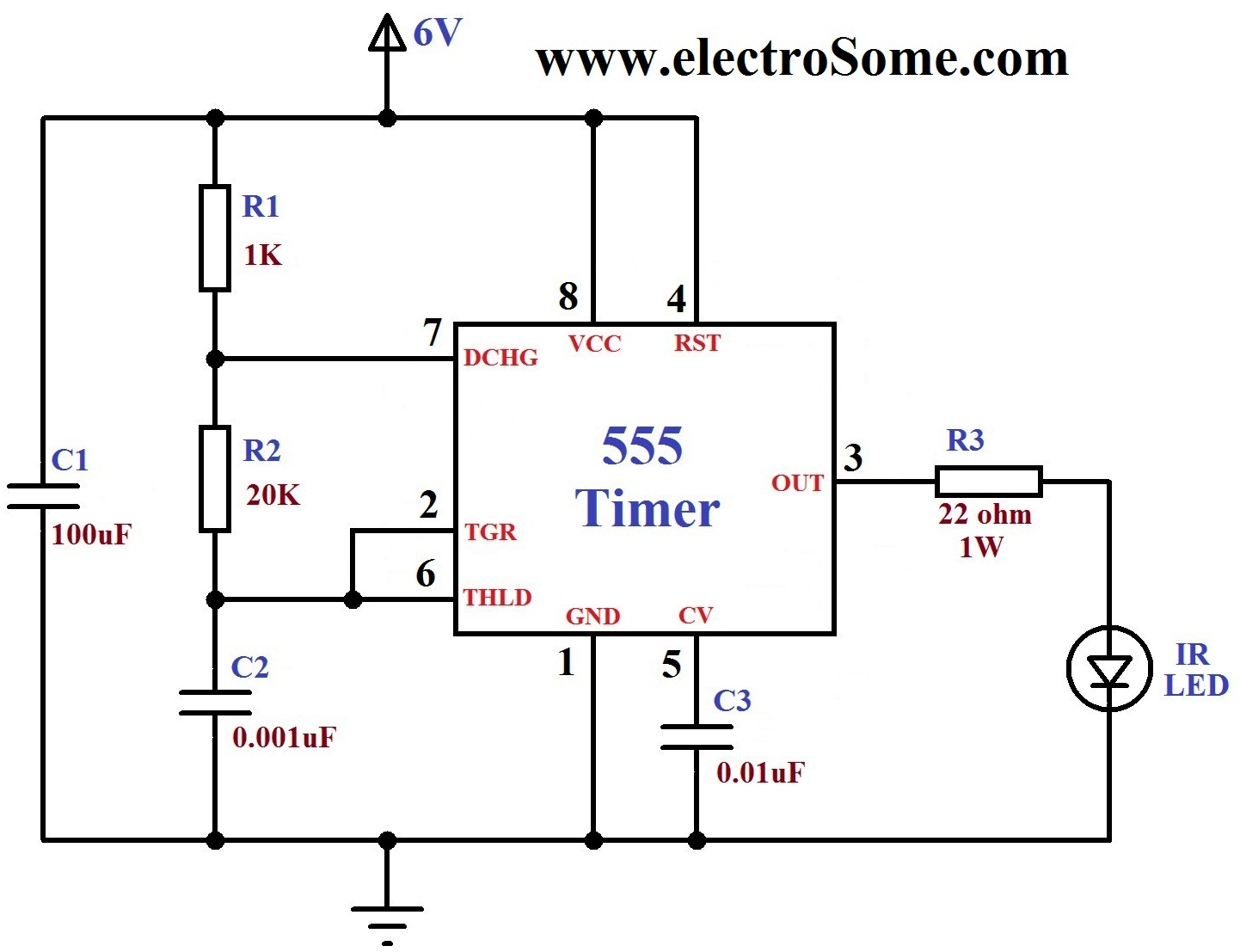
TSOP1738 detects only those signals whose carrier frequency is around 38KHz. Thus it is accomplished using Astable Multivibrator using 555 timer. Please read this article for more details about above circuit.
Note : Output frequency of above circuit is about 35.2KHz. As per our experiment TSOP1738 is detecting it but you will get more range if you use exact 38KHz. You may also use 18K resistor instead of 20K which will produce 39KHz. Better you can try a 20K preset for making accurate 38KHz.


I have made by using CD 4017 it works, but after short time it turn off itself until I press a remote button again
Is there any coding required..?
nice work…bro
Please elaborate.
Hi need help for making a project remote control for any home appliances wothout using any ic
Thanks for your information. You can also contribute your experiments to us. Please mail to [email protected]
There are different kinds of IR leds. Current and voltage will vary. Maximum output current of 555 is 200mA.
It is a general practice to take the resistor wattage twice the dissipated power.
Yes, 35.2KHz is low, but TSOP1738 will still detect it. You can use a preset if you need accurate 38KHz. But for beginners it will be difficult.
What is the expected current for the IR transmitter you’re proposing ? With 1W for the 22Ohms resistor, it’s like you’re expecting a little more than 200ma, which is more than what the 555 can provide. Also, with the supplied R1,R2 and C2 values, the calculated frequency would be around 35.2KHz, which is rather low compared to the expected 38KHz. Wouldn’t it be wiser to use a preset potentiometer for some frequency adjustment ?
Based on a similar idea to yours, I’m planning to create a circuit that will trigger if the appropriate keys count have been pressed on the remote control within a pre-set time.
It’s interesting to see what can be done with basic components such as the 555, 4017 and the TSOPxx.
It will be very difficult without using microcontroller.
i want to do this project but for two or more appliances( 2 channels) but without using micro controller how can you help me plz give some handful detaiol about this thnx????????
There is no special pins for that. I think it is better to use PORTB on change interrupt for that.
Different remotes using different encoding for operation, such as NEC, RC6 etc… Depending upon your remote you have to program it.
could you please tell me the pin name of pic16f887 to receive/differentiate the signal came through transmitter ?? would be very helpful-Thanks.
hi.
i did this with pic16f887 but just simple. i want to use different button for various output.
my confusion is that how to receive/differentiate the ir signal from ir transmitter ?? which pin will be used to receive the ir transmitted signal.
It is better to use a simple microcontroller for that.
if i want to add more than three relay then how can i do it
Please send me the circuit diagram of circuit used for more home appliances using microcontroller and IR Sensor.
and what about in pic16f887 (which for transmit and which for receive) sir????
This circuit is intended for only 1 appliance.. … Better to use a microcontroller, if you need to connect more than 1 appliances..
You may provide input to RESET pin of 555.. .but for decoding you should use additional circuits..
How can we connect more number of appliances to this circuit? Please reply
hallow sir !!!
how to send different code and which pin for transmitter and which one for receiving sir?
thanks for kind help.
You can send and receive different binary codes for each keys.
hi, how to use microcontroller for this??
i mean if i want to use pic16f887 for this than which pin will be used for transmitter and which one for receiver?
please help.
thanks.
NO need to add any programs…. When you press any key on the remove .. the relay will be energized… and in the next press it will de-energize..
after completing the circuit,how will the remote work?that means should we add any programs??
No, TSOP1738 is designed for 38KHz
hey can i achive ir transmission at 70khz+ frequency ??
Try changing TSOP1738… Make sure that your power supply is 5V…
my power supply is ripple free but when circuit is connected to supply the 2 leds start glowing continously . without any signal from remote given the relay energises and leds start glowing one by one until supply is disconnected. plz help
You can use a capacitor for that.. It is already in the circuit diagram…
Make sure that your power supply is ripple free… and tsop1738 is working…
Use the following links :
https://electrosome.com/power-supply-design-5v-7805-voltage-regulator/
https://electrosome.com/transformerless-low-cost-power-supply/
im getting 4.9v – 5.5v at output of tsop1738. its faluctuating thats why the transistor is getting on and off simultaneously. how can i keep the output voltage of tsop1738 constant and not faluctuating ?
can you give me a 230V TO 5V regulator circuit to this IR circuit.i searched and i got but it is not working.if you can.please give a digram.
Understand the working of the circuit before making it… If you understand how it works.. you can easily provide signals manually..
Just understand how TSOP1738 works..
how can i do that?
Yes, better to use a microcontroller for that…
Yes..
how can operate more than 1 devices in this circuit in different
sequence like a tv remotes , 1 for volume ,2 for channel like that, i
think that will need a programming,,,,,,..
how can operate more than 1 devices in this circuit in different sequence like a tv remotes , 1 for volume ,2 for channel like that, i think that will need a programming,,,,,,……
100uf & 33uf capacitors are electro capacitors?
For every devices there will be two terminals… Phase (P) and Neutral (N)
Connect Neutral directly to that device..
Connect Mains Phase to COM (Common) terminal of relay
Connect Device Phase to NO (Normally Open) terminal of relay
Can you tell exactly how to connect a appliance , suppose i want to connect a mobile charger then what will be the connections ?
It varies for different models..
5v relay has the same config. isnt it ?
Please check the data sheet of the particular relay… If you are talking about 12V pcb mountable relay…
2 pins on one side is NO and NC…
center pin on the other side is COM…
2 side pins are coil
i think the 2 pins are for NO and NC and the three pins are for Coil and the middle one is common.
i think the 2 pins that are on one side are for coil and the 3 pins are of NO ,Pole and NC. If i m worng plz correct me .
Then use 4 cells… in series… it will give 6V….. The above circuit will work on 6V without any problem..
can i arrange 3 cells in parallel to give 4.5v as the supply to circuit ?
Don’t connect 9V battery directly to the circuit.. you need to reduce it to 5V.. use 7805 voltage regulator IC…
plz tell me how to connections of the relay . i mean there are 3 pins on one side and 2 pins on other side of relay so which pin in NC and NO and for Coil plz tell .
can i give vcc to circuit by placing 9v battery ?
It will work.. even if they are not used….. It is prescribed in the datasheet.. .
Q1 inverts the output of IR sensor.. capacitors connected to transistor avoid unwanted triggering…
Q2 drives relay… D3 acts as flyback diode to avoid circuit damage due to relay back emf currents..
You may use an NPN transistor by making necesary changes in the circuit..
yeah i didnt get why was pnp transistor was used ? can anyone explain plz .
what will happen if there was no R1 and C1 at pin no. 2 of IR receiver ?
plz can anyone explain the use of Q1 , Q2 and D3 . i m trying to make the project report so i need to explain them .
what is the work of the pnp transistor Q1 can a npn transistor replace it ? and plz tell the use of Q2 and D3 too. thank you
thank you for help.
Sorry, we haven’t those photos..
Yes, it will be same.
Pls send ur bread board connection photos to [email protected]
the connections for hcf4017 will be same as cd4017 in the circuit ?
and also i didnt get how to assemble the relay on pcb
Yes you can use that IC..
That resistor I used is 100 ohm as recommended in the datasheet of TSOP1738…
It will work fine even if you use 33 ohm or 47 ohm resistors..
NO,,,, , an NPN transistor can’t be replaced with PNP without additional circuits..
will IC HCF4017BE work in place of IC CD4017 ? on what basis is the resistor on pin no. 2 of TSOP 1738 is decided ? i have seen circuits having 47 ohm resistor and i m having only 33 ohm resistor, will it work with 33 ohm resistor?
There is a RELAY in the circuit,, which controls the light…. instead of switch..
Check your circuit by manually provide signals (5V and GND) to the circuit instead of TSOP1738, 3ed PIN
i completed this circuit but it doesn`t work.. when i give the power to circuit,one LED is turnon then i pressed TV remort keys but didn`t work.. what can i do for that? help me…
Use 0.1uf ceramic capacitor.. …
use 16V capacitors for 100uf and 33uf
What are the Voltages of this Capacitors? (0.1uf , 100uf , 33uf , )
Yes, ofcourse
I don’t get your question.
Hi, Is it sense the TV remote signal also.
If I want to retain the NO or NC position at different IR signal even after the power off and on again what have to be done ??
Yes, it should be possible without microcontroller, You have to design that circuit.
This is a very good concept.
But suppose if i want to control suppose 4 devices at random manner.
(i mean among 4 devices…1st i turn ON ‘C’ device n then ON to ‘D’ then ON to “B’ then to OFF “C”…means randomly n random action)
Does it possible without Microcontroller??
Thanks for the feedback..
YOU CAN ALSO USE HS0038 IR RECIVER at PLACE OF TSOP1738 IR reciver
THANKS FRIEND ITS COMPLETED AND WORKING PROPERLY WITH TV REMOTE , THANK YOU SO MUCH.
It will work with TV remote… Make sure that your TSOP1738 is working……
Just make the Transmitter Pair and verify that IR sensor is working properly..
Try the following link for more details . .
http://electrosome.com/ir-transmitter-receiver-led-tsop1738/
i have made this ckt but it not work with tv remote (still i have not made transmitter ckt) , my ckt is ok i check many times then what should to do ,, .is i must be make transmitter pair ckt using 555 timer please give me details.
Yes,this circuit works. I have made it
WHAT IS THE FUNCTION OF C2 & C3 IN REMOTE CONTROL RECEIVER CIRCUIT?
Can we use BC548 npn transistor instead of pnp BC558 transistor ?if not please tell the reason.
go in MATLAB and go in embeded TSE link . it requires Minimon software to be installed. C166 interface card (microcontroller board is programmed)
assalam u alaikum
i like this circuit a lot if it will be working and if want to connect more than application like light bulb which also operate one by one as well as all work with same time then plzzz tell me about circuit diagram i will be thankful to u a lot
also can u send me different types of circuit which is interested and usefull on my mail id
my mail id is hafizhamid111@gmail,com plzzz i again tell u thankfull
Yes.. it will work just by connecting the power..
WHERE IS THE BUTTON OF REMOTE CONTROL ? THERE MUST BE A SWITCH >>>
OR IT’S WORK JUST BY CONNECT THE POWER AS I THINK ?
Use UART communication between PC and PIC………
please help me… how to interface Mat lab programs with pic Micro controller…
There is no code for this circuit.. as it doesn’t uses any microcontroller..
from where i got the code of this project
Yes it will work..
is this circuit really work? because i have tried this http://www.electronicsforu.com/electronicsforu/circuitarchives/view_article.asp?sno=235&article_type=1&id=352&tt=unhot circuit and it doesn’t work, i dont know where is wrong because i follow the circuit exactly. plz do help me.