

LED Chaser using 4017 Counter and 555 Timer
Contents
Introduction
A simple LED chaser hobby circuit can be made using 555 timer and CD4017 counter IC. You can use this circuit for decorative purposes. By modifying the circuit in a proper way, you can even use this to control lights working on AC mains.
Components Required
- CD4017 Counter IC – 1
- 555 Timer IC – 1
- LED – 11
- 680Ω Resistor – 11
- 10KΩ Resistor – 1
- 10KΩ Variable Resistor – 1
- 10μF Capacitor – 1
- 0.01μF Capacitor – 1
- 9V Battery / Power Supply – 1
Circuit Diagram
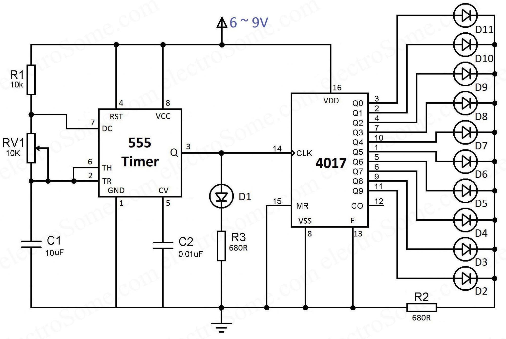
You can see that the 555 timer wired as an astable multivibrator and its output is connected to the clock input of 4017 counter IC. The output frequency of the 555 timer is determined by the resistors R1, RV1 and capacitor C1. VCC (8th pin) and GND (1st pin) is connected to the power supply. Reset (RST – 4th pin) is connected directly to the positive power supply to avoid accidental reset of 555 timer. Control Voltage (CV – 5th pin) is not used, so to avoid high frequency noises we are connecting a capacitor (C2 – 0.01μF) to the ground.
LED D1 is used to indicate the output of 555 IC and the resistor R3 is for current limiting.
Similarly VDD (16th pin) and VSS (8th pin) of the CD4017 IC is connected directly to the power supply. Clock enable (13th pin) is an active low input, so it is connected to ground. Clock input (14th pin) is connected to the output of 555 timer. Each decoded output pins (Q0 ~ Q9) is connected to LED. Resistor R3 is used for current limiting. Only one resistor is required for limiting current through all LEDs since only one LED will turn on at a time.
Working
You can easily understand the working of the circuit from the above animation. As I explained above, 555 timer is wired as an astable multivibrator. Please read the article Astable Multivibrator using 555 Timer for detailed explanation. So the 555 will produce square wave output and which will act as a clock for the CD4017 counter IC.
You can see that for each high pulse output of 555, the output of 4017 is incrementing by one. Output frequency of 555 astable is given by the following equation.
- Output Frequency = 1.44/((R1 + 2RV1) * C1)
So you can easily change the output frequency of above circuit by varying the preset RV1. By this we can change the LED chasing speed.
Tip
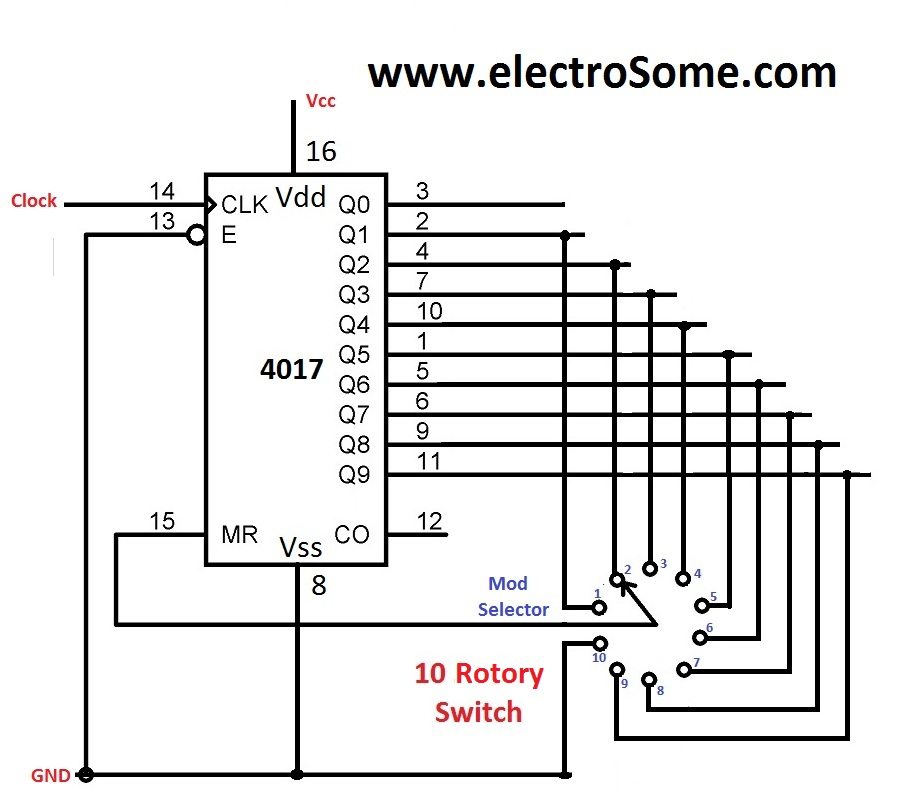
You can make use of Reset input (15th pin – MR) if you want to reduce the number of LEDs. Just connect the output pin to the reset pin as shown below. For eg. if you need only 2 LEDs, you can connect Q2 (4th pin) to Reset pin.
PCB
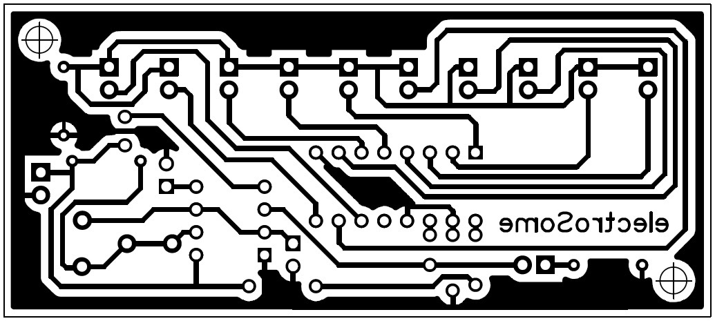
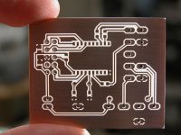
Here you can see the top and bottom view of the PCB design. You can download the PDF files of PCB at the end of this article.

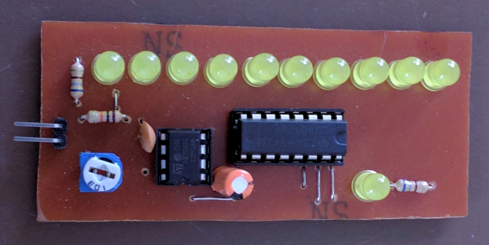
Here is the one we made in our lab.
Video
Download Here
You can download the PDF of the PCB here.

this circuit is very good for beginners who has little bread boards and only few wires. thankyou from me.
I thoroughly enjoyed building this circuit. Would recommend!!
I am a beginner and this content is very useful for me because this article guide me to do what I was willing to do. The most I like in the content is rotary switch part.
Thank you
Anything greater than 16 should be good.
10 uf… How much volt??
Yes it is possible. But you need to redesign the circuit a little bit to support current and voltage of your LED strip.
With this circuit, can i connect the 5meter led strip light on each channel ?
Sorry, we are not selling any kits.
I need a kit
Brief and clear to the point
You only need (2) 680 resistors to work just like the schematic shows. One other thing I noticed the schematic shows the incorrect wiring from the timer to the variable resistor. I corrected this by following the traces on the PCB diagram. After several attempts at trying this I just now got it to work properly.
my first time doing these list says 11 680 resisters but don’t see where they go ? can you help me
print it from any of laser printer . use toner transfer paper
Sir can give u contact me on whats app no +918474901558. I need your help for more project . How i print on a4 size for etching